
Arc Flash Considerations for Utility and Construction Activities: Part II

This article concludes a two-part discussion of protection strategies against arc flash and shock hazards. Here you will read about two topics: (1) arc flash and shock hazard labeling for industrial, commercial and generation facility electrical exposures, and (2) methods used to determine the level of PPE required.
The previous article (see https://incident-prevention.com/blog/arc-flash-considerations-for-utility-and-construction-activities) mentioned that utilities follow OSHA 29 CFR 1910.269 and construction companies follow either 1926 Subpart K or 1926 Subpart V, depending on the job site. It discussed arc flash and shock hazards as a basis for selecting appropriate PPE to protect against each hazard. It also reviewed the consideration and provision of daily workwear and flash suits as well as voltage-rated gloves for low- and high-voltage work. Part II will explain the methods used to determine the level of PPE required through an arc flash incident energy analysis or engineering study. Equipment-specific labeling is the most widely used method to communicate the level of protection to workers. Arc flash and shock labeling will be presented using examples and serve as a backdrop to the introduction of key terminology used in electrical safety.
Arc Flash and Shock Labels
An arc flash label informs a worker of both shock and arc flash hazards. In certain cases, it may provide risk mitigation information. Labels generally are placed on switchgear, switchboards, panelboards and motor control centers at industrial plants and power generating utilities. In transmission and distribution work, and occasionally in large industrial plants, procedures and training – instead of labels – are used to inform workers of arc flash hazards during bucket truck operations, ground-level work in high-voltage switchyards and work on overhead power lines. Transmission and distribution do, however, utilize labeling inside relay houses; on metal-enclosed medium-voltage and low-voltage distribution equipment used for switchyard 480-volt power; and on 208-volt lighting and control systems.
Below are examples of two labels. Note that these are examples only and not based on actual studies or labels installed at any location. Figure 1 shows an example of a “Warning” label and Figure 2 shows an example of a “Danger” label.
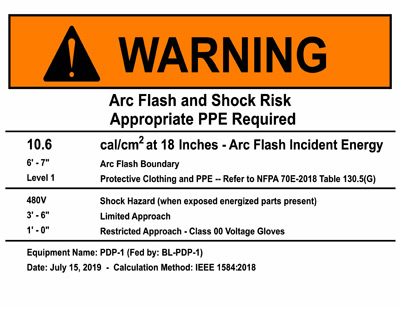
Figure 1
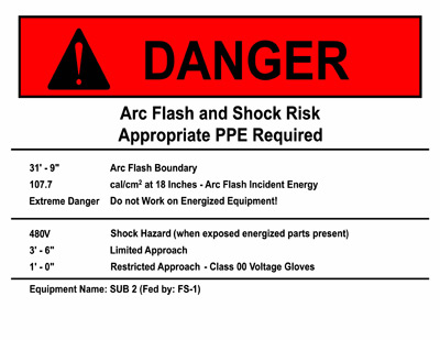
Figure 2
Labels can be customized in any number of ways, but they should always convey certain minimum information.
The incident energy value on the label quantifies the thermal energy reaching the worker’s head and body at the working distance if an arc flash were to occur. If the worker gets closer than the working distance indicated on the label, the energy will increase, and vice versa. Consider troubleshooting where the worker may need a closer inspection and ends up closer to the source of the arc.
Unprotected workers must remain outside of the arc flash boundary. This boundary is where the incident energy decreases to a tolerable level. Consensus standards place it at 1.2 cal/cm2, while OSHA allows up to 2 cal/cm2. Both of these boundary condition energies will cause discomfort to bare skin, but this is 100% curable in healthy workers. Aiming for 0 cal/cm2 usually provides an unrealistic boundary distance and is not used.
OSHA-recognized consensus standard NFPA 70E defines workspace boundaries for these exposures. The NFPA 70E exemption for electric utilities is defined in NFPA 70E-2015, Article 90, B40.2(B)(4), “Approach Boundaries.”
The voltage listed on the label informs the worker of the correct glove class for shock protection, the correct selection of tools for live work and the appropriate working distances for the shock hazard. Transmission and distribution switchyards employing lineworkers default to the minimum approach boundary, while power plant electricians are more comfortable with the limited approach boundary and restricted approach boundary. This terminology is described in OSHA and NFPA 70E.
Some sites choose to indicate the equipment name and the source on the label, but these are best kept separate from an arc flash label. Arc flash labels may become illegible due to environmental conditions; it is then best to maintain an engraved type of equipment name label.
Adding a date to the label is optional. The consensus standards require the arc flash incident energy calculations to be reviewed at periods not exceeding five years. If the label is dated, does the plant change out accurate labels every five years? If the labels aren’t changed out, will field workers or contractors trust an outdated label? Most transformers and power circuit breakers are not changed or altered every five years, implying that the incident energy will remain unchanged for large parts of the plant and the label will remain valid. That isn’t the case when a label is dated.
Finally, the label identifies the arc-rated and shock PPE required, either directly or indirectly. Some examples of indirectly referencing the required PPE are training workers to interpret the incident energy levels, including wording such as “daily workwear” or “flash suit,” or using a site-specific PPE level table. Many larger utilities have chosen to adopt NFPA 70E for their generation plants, as it provides clear guidelines on labeling requirements. High-voltage switchyard work with transmission and distribution follows OSHA and the NESC instead of NFPA 70E.
There is a level beyond which live work is prohibited, dictated by the maximum level of arc-rated protection available to workers. The maximum level of protection currently available is 40 cal/cm2. Forty cal/cm2 was an arbitrary number chosen by a consensus standard believing that arc blast occurred above this value and thermal protection alone was inadequate. Once the maximum level of arc-rated protection is established by engineering analysis, ensure that any equipment with higher incident energies is labeled using a red “Danger” label prohibiting any energized work. All other equipment should be labeled with an orange “Warning” label as per ANSI Z535.
Arc Flash Engineering Studies
The arc flash boundary designations found on the labeling above come from engineering arc flash studies following accepted practices found in both OSHA Appendix E and Annex D of NFPA 70E. Commercial software – such as SKM Power*Tools, ETAP and EasyPower – is used for systems less than 15 kV, and ARCPRO is used for systems rated 15 kV and above, such as high-voltage switchyard modeling. Most software packages are now updated to the NESC 2017 tables and may accommodate >15-kV studies. Generating plants are fairly complex due to multiple layers of redundancy in supply. It is common to find one circuit breaker that is capable of being supplied from various upstream sources. Engineers undertaking the arc flash hazard analysis need to work with the plant operations and engineering departments to ensure that the correct information is provided for labeling purposes. The highest energy may not necessarily be preferred since it could rarely be used as an operational configuration. As an example, a switchboard was calculated to be less than 8 cal/cm2 when fed from the utility source and required daily workwear. This particular setup was repeated over several generating units and operated fairly regularly. In the unlikely event of a total blackout, a black-start generator could be used; however, the energy then increased to above 40 cal/cm2. The plant decided to utilize the 8-cal/cm2 label and drafted a procedure for black-start operating, which mentions the higher arc flash energy. In cases like those, OSHA requires that training take on a prominent role. Workers must be trained, and the plant must ensure that all workers understand which operating configuration is mentioned on the label and where to obtain the correct arc flash information if the operating configuration has changed.
Studies should be independently reviewed to ensure accuracy of the model, and the inclusion of operations is critical to the successful buy-in of the study data. We were recently told of an engineer who completed an arc flash study review using a central database without speaking to anyone on-site or performing a site visit. Although the study review may be valid, there is a lot of operating information that is unlikely to be found in drawings alone. In the case mentioned, some operations personnel questioned the validity of the labels, and some even refused to operate certain pieces of equipment.
Construction sites make use of temporary power, not only at the work site, but also at the contractor’s site-established workshop. Construction site managers should ensure that the plant engineering team assists them with the integration of their electrical system. If construction companies utilize their own transformers and generators, it is fairly standard to get them modeled and determine the arc flash energies. If not, then construction companies must budget within the project to provide this information. Two recent temporary power installations were calculated to exceed 20 cal/cm2. Had the power plants’ safety requirements not mentioned arc flash protection, it is unlikely that a mechanical contractor would have identified this hazard. OSHA requires the employer to inform the contractor of the site’s hazards, and the contractor shall protect its workers from such hazards. Contractor safety is thus a joint effort of the two parties.
Conclusion
This article, as well as Part I, discusses PPE for shock and arc flash protection, as well as methods to determine and communicate levels of protection to workers in the field. An arc flash engineering study is the most common approach to estimating the arc flash incident energy, which is required to establish the correct equipment labeling. Since the PPE program likely will utilize more than one set of arc-rated PPE, on-site equipment labeling is crucial to ensure that workers use the correct protection for the correct activity at the specific location. The engineering study also meets OSHA’s requirement for the estimation of the arc flash incident energy and provides important details such as the voltage level, safety distances and boundaries, and the required PPE for both shock and arc flash.
These articles cover a limited topic in the broad field of electrical safety. They are meant to supplement other important electrical safety considerations, including the written electrical safety program, hazard identification and risk assessment techniques, training, auditing and maintenance.
About the Authors: Zarheer Jooma, P.E., joined e-Hazard U.S. (www.e-hazard.com) in 2016 after 10 years of managing e-Hazard South Africa. He earned a master’s degree in electrical engineering and is a registered professional engineer. Jooma performs electrical network design, arc flash studies, electrical safety training and auditing. He has convened and chaired arc flash safety standards and is a member of both ASTM and IEC electrical safety standards committees regulating arc-rated PPE. Jooma currently is working on updating IEEE 1584.1 regarding the scope of arc flash engineering studies.
Hugh Hoagland is one of the most active trainers and researchers in electrical arc protection. His NFPA 70E and OSHA 1910.269/NESC training programs are used by many Fortune 500 companies and governmental agencies. Hoagland has developed testing since 1994 and has performed over 50,000 electrical arc tests (www.arcwear.com). His publications are numerous in IEEE and safety magazines, and he helped invent many arc-rated materials used today.