Train the Trainer 101: Practical Personal Protective Grounding
In the last 10 years I have consulted on dozens of induction incidents, eight of which resulted in fatalities. There were commonalities in each one. Just about every Incident Prevention reader will agree that one of the topics that receives the most attention across the power industry – in writing, training and conversation – is personal protective grounding (PPG). Not a week goes by that I don’t email or talk to someone about PPG and, in particular, about dealing with induction.
At iP we discuss and share information as well as news about incidents involving induction, and yes, they do occur at an alarming rate. I can’t point to any empirical evidence, but my colleagues and I think we, as an industry, are the reason for the confusion over PPG issues. We have been slow to evolve from grounding for the purpose of stabilizing electrical systems and protecting equipment, to grounding for the protection of workers. Even the language of the OSHA standard, to some, seems vague, contradictory or too technical. The ANSI standards establish sound procedures for protective arrangements, but they are not training resources for craft workers. Now, as infrastructure loads and system voltages continue to increase, there are corresponding hazards that were not even discussed just a generation ago. Those hazards are resulting in incidents and, worse, preventable incidents that risk the lives of power-line workers.
The Six Principles
My colleagues and I have consulted with companies that have training and 300-page grounding procedures manuals that didn’t prevent induction fatalities. The common thread among the fatalities was that the crews involved simply didn’t see the hazards, usually because they didn’t understand the simple principles involved that might have prevented them. I believe that if qualified workers understand the following six principles about current flow, including information regarding grounded systems, they can make the appropriate decisions about how to protect themselves in the hundreds of scenarios they may face over their careers.
Principle 1
Current flows in grounded systems the same way it flows in ungrounded circuits.
Principle 2
Current in parallel systems takes every available path inversely proportional to the resistance of the path. This means interconnected systems will have current in every path, and low-resistance paths will have more current flowing than high-resistance paths.
Principle 3
If you can’t quantify it, you must assume it is deadly and protect yourself accordingly. This means you can’t make assumptions regarding the level of induction. If you can’t calculate or measure for it, you must assume it will be there and take the necessary precautions, like bonding to create areas of equal potential.
Principle 4
It takes about 50 volts to break the electrical resistance of your skin. The voltage required to break the electrical resistance of your body increases when you don nonelectrical barriers like shoes or gloves. If you use rubber gloves, the required voltage increases substantially.
Principle 5
This principle addresses the current it takes to harm you. Charles Dalziel’s empirical data from his experiments in the 1950s and 1960s showed us that a 155-pound lineworker could withstand 91 milliamps for 3 seconds before ventricular fibrillation (see www.hubbellpowersystems.com/literature/encyclopedia-grounding/pdfs/07-0801-02.pdf). For that reason, it is widely accepted and used here that 50 milliamps of current is the threshold of exposure that rises to the level of a hazard to workers. It should be noted here that OSHA, in a note to 29 CFR 1926.964(b)(4), uses a 1-mA current (threshold of perception), assuming that a perceived shock (i.e., current higher than 1 mA) could cause an involuntary reaction resulting in a nonelectrical injury.
Principle 6
This principle targets the difference between tripping grounds and equipotential grounds. Grounds installed to trip a de-energized system during an inadvertent energizing will not protect a worker who is not at equal potential with the system path. Grounds installed to trip the circuit, or tripping grounds, may also be used to protect the worker. However, unless they are arranged or installed to create a zone of equipotential, they will not protect the employee from injury either from inadvertent energizing or induction.
These six principles are not codified or written in any training manual. These are things I have learned over the years as important to recognizing and mitigating the risk of induction-related incidents and injuries. But the most frequent issue relates to the first two principles. In PPG, more is not always better. The problem with grounding is that there are lots of interconnections, and then we add them either purposely or by virtue of bonding.
A Test Case
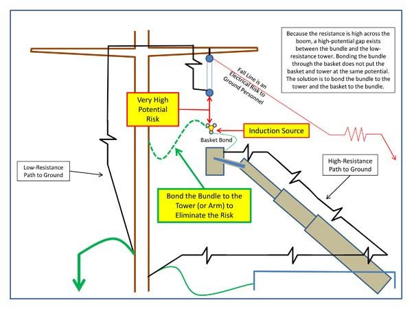
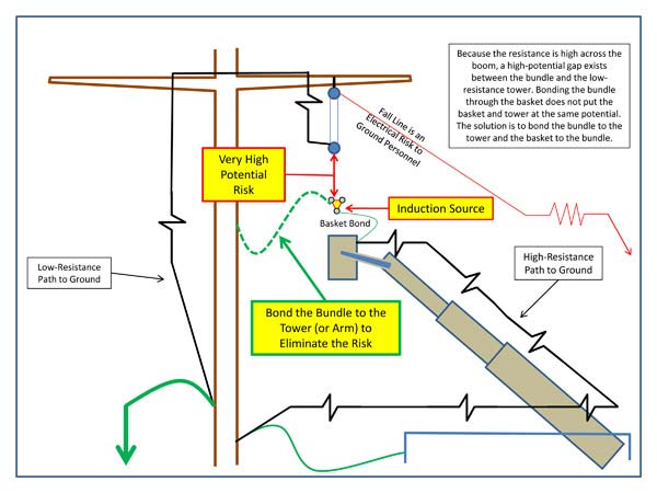
Let’s review an example based on a transmission construction crew’s misunderstanding about resistances in a circuit, which, by the way, is very similar to three of the eight fatal incidents I referred to at the beginning of this article. In this particular case, crews were clipping three-bundle 1590 on a 500-kV new construction on steel mono-poles. The crew correctly knew to bond the basket to the bundle before contacting the bundle to rig for lifting. They used a chain hoist and steel sling rigged from the tower arm to lift the bundle. The bundle was connected to the hoist with nylon slings. Their crane-mounted man basket was grounded at the tower base. The crew’s mistake was believing that bonding the basket to the bundle would put the wire at the same potential as the hoist and tower arm through the connection to the basket and crane. This assumption was incorrect but not uncommon. Once the crew learned the PPG principles, they understood the trap they were building for themselves.
Applying Principles 1 and 2
Current flows in a grounded circuit just like an ungrounded one, and current flows in every available path inversely proportional to the resistance of the path. The source in the example I just described was induction from a 500-kV line parallel to the crew’s build. There was an unknown level of current on the bundle, but voltage was not detectable. This was due to grounded bundle blocks that remained on the new construction and the grounds placed at each end of the two-mile section the crew was clipping. When the basket is bonded to the wire, induction current flows from the conductor, through the boom and into the tower and earth through the tower ground. Up on the wire there is an electrical gap across the nonconductive nylon slings used to rig the conductor to the steel hoist connected to the tower. If a man in contact with the bundle grabs the hoist, he is going to close that gap. The tower has very low resistance compared to the basket and crane. The tower will have more current flowing through that lower resistance than the crane. In other words, the two paths to ground – one through the crane, one through the tower – are not at equal potential. A man in that gap is at risk. The only way to put the two paths at equal potential, or very near equal potential, is to bond the conductor to the tower.
Applying Principle 3
If you can’t quantify it, you must assume it is deadly and protect yourself accordingly. Many lineworkers may have worked in a scenario similar to the aforementioned example and would say they’ve done it that way hundreds of times and never felt a thing. And that may be true, especially if they were working in leather gloves. In their case, it’s possible that the voltage across the open gap between the wire and hoist was only 25 volts, but suppose it was 1,800 volts. What if it was 25 volts that morning because the nearby line only had 80 amps on it, and then they switched it at 10 a.m. and it had 300 amps on it a split second later? You can’t quantify the risk and assure there is none, so you must assume it is deadly and bond across the gap.
Applying Principles 4 and 5
It takes about 50 volts to break the electrical resistance of your skin, and more than 50 milliamps of current is hazardous to workers. It is true that when the basket was bonded to the tower, the tower had current flowing on it at the ground connection. We already know about the resistances and current flow. The tower grounds are very low-resistance, and the crane ground is connected to the terminal stud for the tower ground. The majority of the current on the crane goes into the ground. The tower voltage at this point is measurable between the terminal ground and remote earth. Remote earth is some point on the ground away from the grounding electrode conductor from tower to ground rods. That voltage is developed across the resistance of the earth. There is another resistance where voltage can now be measured. That is the gap between the wire and the tower. That gap could easily have 20 volts or 1,500 volts or more depending on the current flowing in that grounded bundle. And if the bundle block on that structure is grounded, there is another gap that will appear as soon as the conductors are lifted from the bundle block. By the way, I know of two instances in which the induction current was so high that rope slings – and on another occasion, nylon slings – caught fire.
Applying Principle 6
Although it happens, we rarely hear of someone closing on a grounded line. In construction, the more likely scenario is losing your pulling sag or rigging, resulting in your new conductors falling into an energized line. If that happens, your grounded travelers are going to do their job, provided the lineworker who installed them brushed the clamps and connections. Grounded travelers often get overlooked. Several sets of grounded travelers provide multiple paths to earth, helping to manage fault current and reducing current rise at the work location. But the only grounds that will protect employees are those rigged to bridge or jumper around them, preventing voltage rise across their bodies where they are between potentials like travelers and tower, tuggers and earth or conductors and reel trailers.
Employers struggle to identify risks and teach procedures. There isn’t room in this article to look at all of the grounding scenarios out there, and you may find some additional basic principles not discussed here. Send us your comments and training ideas. We hope that providing understanding and principles will give your lineworkers more tools to identify and mitigate induction risks.

About the Author: After 25 years as a transmission-distribution lineman and foreman, Jim Vaughn has devoted the last 17 years to safety and training. A noted author, trainer and lecturer, he is director of safety for Atkinson Power. He can be reached at jim.vaughn@atkn.com.
Editor’s Note: “Train the Trainer 101” is a regular feature designed to assist trainers by making complex technical issues deliverable in a nontechnical format. If you have comments about this article or a topic idea for a future issue, please contact Kate Wade at kate@incident-prevention.com.

