
The Evolution of Personal Protective Grounding: Part 1
Before safe and effective PPG methods emerged, pioneering lineworkers navigated their worksites with limited grounding knowledge, equipment and procedures.
Personal protective grounding, or PPG, is arguably the most critical safety procedure affecting contemporary lineworkers. Over time, it has evolved to include numerous significant elements that contribute to the success of today’s comprehensive methods and procedures.
To adequately address these elements, this article will be presented in two parts. Part one, which you are now reading, covers PPG’s early years. Part two – scheduled to be published in the October-November issue of Incident Prevention – will cover the critical testing and development that led to the methods and procedures currently in use.
1890-1910: The Beginning
Early power systems were relatively simple. A small generating source was connected to a line that served a small number of customers, or sometimes just one. If a line needed to be worked on, the generator was simply shut down while the lineworkers completed their tasks. There were no other sources of energy or adjacent lines to be concerned with. Some early systems, such as one in Niagara Falls, New York, included parallel lines built from the generating station to the load center. This allowed either line to be de-energized for work while the other line provided service.
As power systems were expanded and interconnected with multiple energy sources, clearing and working on lines and equipment became increasingly hazardous. Disconnects, switches and other devices were developed to isolate equipment and sections of lines. But with no established clearance procedures, accidents began to occur in which lineworkers were electrocuted by inadvertently energized lines. They were also introduced to the hazards of induction from adjacent energized lines. During this period, there was virtually no use of protective grounding.
1910-1930: Initial Mitigation Measures
Lighting streets in larger cities was the first widespread use of electric power in the 1890s. Series circuits supplied several arc lamps. Because streetlight circuits required occasional work, accidents happened when station operators inadvertently closed switches while work was in progress. To improve safety, the industry began to employ switches that could be closed to ground series streetlight circuits after opening them.
As the network of power lines grew, lineworkers working on de-energized lines began to feel the impact of induction from adjacent lines. They soon discovered they would not get “bit” by induction if they connected a jumper from the conductors they were working on to earth.
The next protective grounding measure, developed in the early 1900s, was the portable grounding wire. Its use involved connecting one end of a bare wire to earth or, in some cases, a water pipe or fire hydrant. A rope was thrown over all phase conductors. The opposite end of the wire was pulled over the conductors and tied to an object on the ground so that it made positive contact with the phase conductors.
A slight improvement to the wire method was the grounding chain, a long chain typically made of copper, brass or Copperweld. One end was connected to the ground source; the other was pulled tight over the conductors with a rope. This method was included in the 1928 first edition of “The Lineman’s Handbook,” known today as “The Lineman’s and Cableman’s Handbook.” The original handbook emphasized the importance of always (1) connecting the grounding chain to the ground source before pulling it over the conductors and (2) removing the chain before disconnecting it from the ground source.
Little information exists about how underground systems were grounded during this early period. Power companies in large cities with downtown underground systems utilized a variety of homemade grounding devices for equipment in manholes. Initial efforts and development focused on grounding overhead lines, followed by underground. Most power companies developed their own methods and tools for grounding lines and equipment.
No documentation exists from these early periods to suggest that lines and equipment were tested before protective grounds were installed. One of the first testing efforts, developed by Pennsylvania Water and Power, required the lineworker to throw a crescent wrench tied to a conductor that was connected to the grounded tower with a 5-amp fuse. If the line was energized, the fuse would blow.
1920-1940: Grounding Sets with Insulating Handles
In the 1920s, some power companies developed wood-handled protective ground sets. This led to the cluster-type arrangement, in which three conductor jumpers were connected to the junction, where another longer conductor was used to connect to the ground source. Each phase jumper had its wooden handle, which resulted in an entire ground set assembly. These improvements provided a more effective method for grounding conductors and allowed lineworkers to position themselves at a safe working distance in the event an energized line was inadvertently grounded.
Before the 1930s, protective grounding of lines and equipment was not a standard practice for all power companies. In many cases, it was left up to the line crew foreman to decide whether grounds were necessary. By the 1950s, however, protective grounding had become a standard practice and was included as a requirement in power company safety rule books.
Here are two interesting rules from the 1929 Penn Central Light & Power Co. safety rule book:
- “Rule 251 b. When lines or apparatus are killed for work, they shall be grounded and shorted on both sides of the location where the work is going to be done, regardless of whether there is more than one source of energy.”
- “Rule 251 d. Grounds shall never be placed on the same pole or tower where the work is to be done, for when moving the conductor, the ground might become detached. The placement of grounds shall be at least one span away. Under no circumstances shall work be done on a line over one mile from the point of grounding, as sufficient static might be picked up over a greater distance to cause an accident.”
By the 1930s, protective grounding was becoming standard practice for working on de-energized lines and equipment. These two general grounding rules were established and implemented by power companies:
- Grounds shall be installed between the source of energy and the work area.
- Grounds shall be installed in a manner that grounds and short-circuits the conductors.
Up to this point, no comprehensive engineering studies had been conducted concerning protective grounding’s effectiveness in limiting current passing through a worker’s body. Most grounding equipment was made by power companies, with no standardization and limited testing. Procedures varied considerably among companies and regions, and while the number of accidents involving electrocutions had gone down, it was still excessive. The two general rules noted above evolved into an industry-wide practice known as “bracket grounding,” during which grounds are placed on both sides of the worksite.
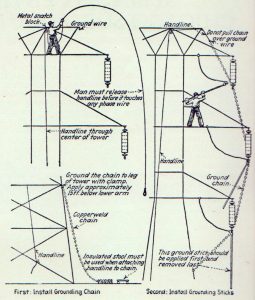
An interesting graphic created by the Public Service Company of Northern Illinois highlights a 1929 procedure the company developed to ground 66- to 132-kV lines. As shown below, the handline was used to pull a grounding chain over the conductors, along with applying individual grounds to the conductors. Lineworkers were required to wear rubber gloves throughout the process.
1940-1950: Understanding Dangerous Current Levels
Prior to the 1940s, there were no recognized studies on the effects of electrical shock on the human body relative to current and voltage levels. Then, in the late 1940s and early 1950s, Charles Dalziel (1904-1986) – a professor of electrical engineering and computer sciences at the University of California, Berkeley – performed considerable research regarding shock injuries to humans and animals.
Dalziel’s research led to information that could be used to evaluate the effectiveness of various protective grounding methods. Here is a list of his key conclusions:
- The minimum current detected by the human body is 1.2 mA.
- The average let-go threshold of current is 9 mA.
- Ventricular fibrillation thresholds may occur above:
- 03-second shock time duration: 1000 mA.
- 3-second shock time duration: 100 mA.
Thanks to Dalziel’s research, the industry now had credible information it could use to evaluate and optimize PPG methods. That information, which remains relevant today, would eventually lead to several considerable safety improvements for electrical workers.
Conclusion
Hazards abounded in the early days of electrical line work. Industry pioneers navigated the unknown with limited PPG knowledge, equipment and procedures. Through trial and error, more effective grounding methods gradually emerged, laying the foundation for essential safety practices. These hard-earned lessons continue to underscore PPG’s critical role in protecting lineworkers.
In the second part of this article, we will explore critical testing that deepened the industry’s understanding of PPG. As tool companies became more actively involved, they contributed to the development and refinement of grounding techniques. Discussion will include key advancements and their importance in ensuring the safety of today’s lineworkers.
About the Author: Alan Drew began his power industry career in 1959. While working for a local utility company, he earned a bachelor’s degree in electrical engineering. Drew was hired as the general superintendent for Clallam County Public Utility District in 1991. He moved to Boise, Idaho, in 1998, where he became an instructor with Northwest Lineman College and advanced to the position of senior vice president of research and development. He is a lifetime member of IEEE and a 2008 International Lineman Museum Hall of Fame inductee. Drew’s most recent accomplishment is writing “The American Lineman,” a book that honors the evolution and importance of the U.S. lineman. He retired in 2020 and is now a part-time technical consultant for Northwest Lineman College.
Sidebar: Line Terminal Ground Switches
In the 1920s, numerous companies began developing substation transmission-line ground switches and disconnects. They were primarily used to ensure the rapid operation of protective devices and to ground lines subjected to induction from adjacent lines. In many cases, line crews used ground switches as protective grounds. This practice was gradually eliminated as real-world experience demonstrated the improved safety of protective grounds at or near the worksite.