
Are Your Temporary Protective Grounds Really Protecting You?
National equipment standards constantly evolve due to near misses and incidents that occur in the field. This evolution results in electric utilities adopting different work methods and procedures, equipment, education and training to keep utility workers and the public safe as every electric utility company builds and maintains the national electric grid.
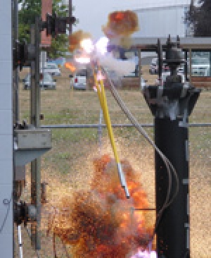
Personal protective grounds are placed between de-energized conductors in case the conductors become accidentally energized. The assembly creates a short circuit, causing the circuit to relay out, and protects a worker from dangerous differences in voltage while they are working. The overall power capability of the national electric grid has steadily increased with the building of new transmission systems with larger conductors, transformers and switch yards. This available power increase results in higher available fault currents and higher asymmetry factors, i.e., X/R ratios. Thermal energy and mechanical energy delivered to the protective grounds increase with both system current and system asymmetry factors. Most substation and transmission systems in the U.S. today have X/R ratios exceeding 10 and many have ratios exceeding 20. With fault currents nearing or exceeding 60 kA and increasing X/R ratios, the mechanical energy can become the limiting factor. However, for worker safety, if a connector or cable fails to survive thermal or mechanical stress, it may fail electrically before the circuit clears, rendering the grounding useless as protection.
Qualification Testing
Adopted in 1983, the ASTM F855 standard specifies the testing needed to qualify equipment used for temporary protective grounding. The test currents and methods in ASTM F855 were based only on thermal energy (e.g., conductor melting) equations developed by I.M. Onderdonk more than 200 years ago. In 2009, testing revealed inadequacies in the test specification when there were higher fault currents with higher X/R ratios. New information indicated that when higher currents were used, especially with higher X/R ratios, the grounding components failed mechanically in the first few cycles while their thermal capabilities were not even close to their limits. ASTM F855 was revised, and a new table, Table 2, was developed for testing with higher currents and higher X/R ratios. To distinguish these newly rated devices from the older ones, they were given the “H” grade designation, e.g., grade 5H components versus grade 5 components. However, it is up to the end-user to ask for components tested to this new requirement, many of whom do not understand the differences and do not know what they really need.
The current ASTM standard allows manufacturers to test and rate grounding components to Table 1, the original table of test values. For example, Table 1 lists a grade 5 clamp with five different currents: 43 kA for 15 cycles or 30 kA for 30 cycles for withstand ratings, or 59 kA for 15 cycles, 42 kA for 30 cycles or 29 kA for 60 cycles for ultimate ratings. Some manufacturers do not declare which values they used to rate their clamps; they simply list the ASTM grade next to each clamp in their catalogs.
Buyer Beware
So, why should you care? Some users interpret a grade 5 rating to mean that the grounding component is good for any one of the five values listed in the table. However, if a manufacturer tested at the withstand rating, 30 kA for 30 cycles – the lowest severity level of Table 1 – there is no guarantee that the components could survive any of the other more severe values. Unsuspecting users would not know that their components would not survive higher current levels mechanically, or even ultimate levels thermally. A few utilities and manufacturers have participated in the higher fault current testing to make certain the material selection and construction of their assemblies meet the standard and will be good for all values in the grade range, but many have not. “Buyer beware” is definitely the best practice for all users of temporary protective grounds. If the user does not have the internal resources to determine protective grounding needs and correctly specify components at the time of purchase, outside engineering assistance should be sought.
Inside the substation, applying grounds on rigid bus is the worst-case scenario due to proximity of the source where the circuit’s inductive reactance is the highest and the resistance is the lowest, creating the highest fault current available. In addition, when an assembly experiences a fault on rigid bus, nearly all the mechanical energy transfers from the bus to the first clamp installed facing the transformer. When an assembly experiences a fault on an AAC/ACSR conductor, almost all the mechanical energy is absorbed in the conductor, creating mostly a thermal test. In the past, many utilities and manufacturers used a test fixture comprised of aluminum multiconductor suspended between insulator supports. When testing, a rigid bus setup should be used to guarantee these same assemblies will protect workers when applied on rigid bus. This rigid bus testing is not a requirement of ASTM F855, so again, users must beware and know what they are buying. Demand copies of the test reports and read them thoroughly to be sure the component is qualified for the application and the current values you intend to use it on.
Changing Viewpoints
High-current testing of different equipment has substantially changed the viewpoints of many utilities. For example, the best-performing clamp is a blind-hole, threaded aluminum, smooth jaw C clamp with stainless steel threaded eye screw that is designed for the specific range tested. The slight design difference of this clamp addresses pressure applied to the conductor, eye screw torque, current flow direction, current transfer area contact, material type and jaw style, which results in superior performance. Testing of different applications has also changed how grounds are being applied. Inside the substation, weld-on studs would not pass a 47-kA fault from any manufacturer. C-style clamps with molded studs have passed up to 68-kA fault currents. Often, if a station is determined to have high fault currents, the utility decides to apply two grounds instead of one to suit the application. It has been found that parallel grounding transfers almost all the mechanical energy to the first clamp encountered by the fault current path. Parallel grounds only work if the equipment being used has been tested to withstand the mechanical energy associated with high fault current and X/R ratio, as appropriate. For example, a single 4/0 assembly can outperform a double 2/0 assembly.
No Substitution
Another compounding issue is that there are several manufacturers of cable, ferrules and clamps. Many users substitute components from different manufacturers. However, there are subtle differences between them and they may not work together to achieve the protection needed. If there is no test report showing that they will pass the most stringent of the grade requirements, then there is no confidence that they will. Manufacturers do not test their own equipment in conjunction with their competitors, so utilities should not substitute different materials during construction; if they do, the liability is on the utility. Variables, such as cutting the strands when stripping the jacket, crimping the ferrules at different locations along the barrel and over-tightening the clamp hardware, could result in failure during a fault. Failures of assemblies can include cables fusing, cable pulling out of ferrules, ferrules breaking or melting, and clamps breaking at different locations. Remember, individual components should not be substituted without valid test results.
Use and Care
Laboratory testing of these assemblies is performed on brand new equipment that has never been weathered, stressed, dropped or mishandled. In reality, grounding assemblies are subjected to this every day. A maintenance program is a must to ensure the integrity of the assembly remains intact. A visual inspection should be done before each use and the assembly should be electrically tested using a current source capable of producing the continuous current rating of each gauge size cable being used. ASTM F2249 specifies test methods for in-service temporary grounding jumper assemblies used on de-energized electric power lines and equipment. Independent studies have shown that testing assemblies at continuous current ratings improves the correlation to actual high-current tests.
The final lesson is to know your grounding equipment and take good care of it. One day it could save your life. Remember the saying: When you’re in the jungle, it’s not the lions or tigers that kill you – it’s the mosquitoes and gnats.
About the Authors: Marcia L. Eblen earned a bachelor’s degree in electrical engineering from the University of Colorado Boulder. She worked for Pacific Gas & Electric Co. for more than 28 years, where she was most recently the principal grounding engineer. Eblen, a registered professional engineer in the state of California, currently consults on electrical safety, grounding and arc flash hazards. She is a member of several IEEE subcommittees and ASTM Committee F18, and has been a voting member of the NFPA 70E Technical Committee since 2008.
Rick Kennerly is vice president of engineering and operations for Bierer & Associates (www.bierermeters.com). He will present “It’s Alive and Grounded,” which addresses protective grounding hazards and solutions, October 1 at the iP Utility Safety Conference & Expo in Louisville, Ky.