Are Your Substations Safe?

Electrical power is a critical service that profoundly affects our daily lives. Without it, we would lose cellphone service, safety on city streets would be compromised because lights would not work, and the quality of life as we know it would diminish significantly. We would have to close schools and hospitals, and most jobs would be eliminated. Much of our food supply also would be critically impacted.
To continue living the life we are accustomed to – and have come to expect – we must have a reliable source of electricity, which starts with generation. Outside the generation station, power typically is stepped up to a higher voltage and usually ends up at a transmission system voltage (i.e., 115 to 550 kV). Transmission substations provide a means to transmit and protect the high-voltage transmission systems throughout the U.S. To distribute the power to homes and businesses, the transmission voltage is stepped down to lower voltages in distribution substations. Both transmission and distribution substations have breakers and fuses to provide system protection, along with many other parts and pieces that provide protection for equipment, personnel and the public, as well as reliability.
To ensure that power is always available, utilities must be diligent – engaging in regular inspections and National Electrical Safety Code (NESC) audits – in identifying conditions that may impact reliability and safety. The NESC has been around for approximately 100 years. Initially created as a guide to help electrical professionals understand safe design and work practices for generation, transmission and distribution systems, it is a culmination of many other standards, some of which will be referenced in this writing. Substations – or “supply stations,” as they are referred to in the NESC – are an integral part of our transmission and distribution infrastructure and have inherent hazards that must be considered.
Electricity is an invisible hazard that can cause loss of life or significantly damage equipment, affecting the reliability we have come to expect. Qualified electrical personnel can easily be shocked or burned when working with exposed energized parts. Low-voltage power can be hazardous, and contact with it has accounted for many deaths throughout the U.S., but the higher voltages in substations introduce other hazardous conditions that typically are not identified within low-voltage systems. Additional substation hazards include:
- Objectionable current flow in the grounding system.
- Induced current.
- Transient voltage.
- Step and touch, or gradient, potential.
- CT open secondary circuit.
- Arc flash and blast from open-air switches and enclosed rack-out breakers.
The NESC provides guidance on protection from these and other hazardous conditions.
Grounding and Bonding
The supply station grounding system is one of the most important parts of substation infrastructure. Unfortunately, it often is the most neglected. A good grounding system starts with a ground grid, which is a series of copper wires or electrodes connected with a cadweld or similar permanent subsurface connection to form a horizontal grid that typically is buried to a depth of about 18 inches. There are several options, but ideally the ground grid should run approximately 3 feet outside the substation fence and the swing of the gate to provide an equipotential area between earth and the fence, reducing the touch potential hazard. The purpose of a ground grid is to achieve the lowest ground resistance possible to all metal parts within a substation to limit step and touch potential and minimize other differences in potential. This is not to say that low resistance is always safe. Some conditions – such as overhead shielded conductors or grounded distribution neutral conductors entering the substation – may be more hazardous with low substation resistance due to higher potential differences. Special precautions should always be considered before any work is done within a substation.
According to IEEE Standard 80, “IEEE Guide for Safety in AC Substation Grounding,” the design parameters of the grid include maximum grid current, fault duration, shock duration, soil resistivity, surface material resistivity and grid geometry, which primarily considers the area of the ground system, conductor spacing and depth of the grid. Once the grid is designed and installed, connections are made to ground and bond all metal non-current-carrying parts within the substation, including the fence, the steel structure and the enclosure of transformers, breakers, regulators and all other metal case equipment. The problem is that there are many old substations, some built over 80 years ago, and the connections likely will have a higher resistance than initially designed. Ground grids should be tested periodically to ensure that they are reliable and effective; testing should include all bonding taps coming from the grid. Refer to IEEE standards 665 and 1050 for generation and instrumentation grounding in power stations.
The ground grid provides very low resistance and good contact with earth. Inversely, the surface needs to be at a high resistance to limit step and touch potential should a fault occur. Table 7 in IEEE Standard 80 outlines typical surface material resistivity, providing examples of the resistivity of various materials, such as gravel. It is recommended that the material chosen should be approximately 6 inches deep.
Fences
Substation fences are required to be grounded to limit step and touch potential and hazardous voltage impressed from transferred voltages, induction, circulating current, fallen conductors, failure of operating equipment, lightning strikes and so forth. To achieve effective fence grounding, bond posts as necessary to the ground grid and run minimum steel AWG #5 wire though the fabric of the conductive fence connected to post bonding wires. Gates shall be grounded at each post, and a buried jumper shall be used to bond one post to the other. Flexible ground conductors (braid style) shall be used to bond the post to the swinging or rolling gate.
Fences shall be a minimum of 7 feet tall, or they must be 6 feet tall with three strands of barbed wire attached to achieve an overall height of 7 feet. Barbed wire shall be effectively bonded to the fence grounding system. Fence shall have a safety clearance zone from exposed energized parts as specified in NESC Table 110-1, but never less than 10 feet.
A sign that warns of the dangers within shall be posted on each gate or entrance and on each side of the substation perimeter fence. For long fences on larger substations, multiple signs may be required. Signs shall meet ANSI Z535 standards.
Openings in the fence or gate should be avoided. According to NESC 110A, “Electric supply conductors and equipment shall be arranged with barriers such as fences to limit the likelihood of entrance of unauthorized persons.” The NESC Handbook notes state, “The perimeter fence is intended to prevent intrusion by animals and unintentional trespass.”
OSHA 29 CFR 1926.966(e)(3) covers restricted entry. Unqualified persons may not enter the rooms or other spaces while the electric supply lines or equipment are energized unless under direct supervision of a qualified worker. Upon entering an attended substation, each employee, other than employees regularly working in the station, shall report his or her presence to the employee in charge of substation activities to receive information on special system conditions affecting employee safety.
Rooms and Buildings
All rooms and spaces in which electric supply equipment is installed shall comply with the following requirements:
- They shall be free of dust and fumes and not used for storage.
- Construction of buildings shall be done with noncombustible materials as much as practical.
- Sufficient ventilation is required to maintain operating temperature of equipment and minimize accumulation of airborne contaminants.
- Rooms and spaces must have proper illumination with minimum 0.2 footcandles in remote outside areas to 25 footcandles in occupied highly critical areas (refer to NESC Table 111-1).
- Slippery floors should have an anti-slip covering.
- Exits shall be clear from obstructions.
- Buildings shall be locked with limited access. Signage requiring qualified personnel only should be posted on the door.
- Floor holes, stairs, railings, toeboards and related items shall conform to NESC 112 or OSHA 1910 Subpart D.
Inspection of Electrical Equipment
Electrical equipment, including idle and emergency equipment, shall be maintained at such intervals as experience has shown to be necessary. Defective equipment shall be fixed or taken out of service. New equipment should be tested in accordance with standard industry practices before being placed into service.
All equipment – including transformers, circuit breakers, reclosers, switchboard cases, operating switch handles, enclosed bus ducts, surge arresters and communications equipment – shall be effectively grounded (refer to NESC Section 9).
Guarding from Live Parts
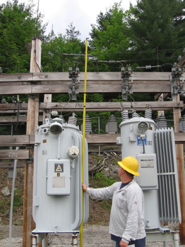
Guards shall be provided around all live parts operating above 300 volts phase to phase without an adequate insulating covering, unless their location gives sufficient horizontal or vertical clearance or a combination of these clearances, to limit the likelihood of accidental human contact. Follow NESC illustration Figure 124-1 and use data from Table 124-1 to determine clearance. If vertical distance to exposed energized parts cannot be maintained, supplement barriers such as rails or fences. A barrier should be at least 3.5 feet high and between 3 to 4 feet away horizontally.
Each conductive part with indeterminate potential to earth – such as telephone wires exposed to induction from high-voltage lines, ungrounded neutral connections, ungrounded frames, ungrounded parts of insulators or surge arresters, or ungrounded instrument cases connected directly to a high-voltage circuit – shall be guarded on the basis of the maximum voltage that may be present on the surface of that equipment. The vertical clearance above grade of the bottom of such part shall not be less than 8.5 feet unless it is enclosed or guarded.
Conclusion
The NESC and associated standards provide a valuable guide for us to design, build, maintain and inspect electrical supply stations. Every electrical professional who works in or around substations should take the time to read and fully understand these standards. Through regular inspections and NESC audits, utilities can identify conditions that may have an impact on reliability and safety.
About the Author: Lee Marchessault, CUSP, is president of Workplace Safety Solutions Inc. (https://workplacesafetysolutions.com).

