


Rethinking Arc Flash Labels for PV Projects
Labels and PPE must be part of a larger system of worker protection that integrates all levels of the hierarchy of controls.
Arc flash labels are a commonplace requirement for photovoltaic (PV) projects. However, arc flash studies and the resulting labels are sometimes treated as check-the-box exercises. In my experience as an engineer, I have found that questions are rarely asked regarding integration of PV arc flash labels into a safe, effective operations and maintenance plan. Engineers who charge by the man-hour can generate these labels all day long, yet they aren’t the ones tasked with donning PPE to perform hot work. A fundamental link is missing in terms of safety.
Essentially, arc flash labels provide employees with critical PPE information when work must be performed near energized electrical equipment. But this could make hot work on energized electrical systems sound routine – and it shouldn’t be, ever.
Consider this scenario that a safety expert presented to students during an electrical safety training class in Baghdad: There is heavy nighttime fighting. After shrapnel cuts power lines to a hospital, the emergency generators don’t start. Do you rush to splice the wires back together, hot, because lives are at stake, time is of the essence, and the task is relatively simple?
The safety expert’s recommended response? An emphatic “no.” Unforeseen hazardous conditions could lead to worker injury or death and additional equipment damage in addition to prolonging the outage.
The bottom line here for workers is to perform assigned tasks de-energized whenever possible. Fully inspect and test to determine the scope of work. Make the necessary repairs, check again, and then safely re-energize. No shortcuts.
A Troubling Perspective
Occasionally a client will say they do not want to see PPE categories above Level 3, which is troubling for two reasons. One, if a job requires live troubleshooting, Level 3 PPE may not adequately protect workers. Two, the client’s perspective excludes any mention of the other five levels of the hierarchy of controls (i.e., elimination, substitution, isolation, engineering controls and administrative controls), plus it disregards the fact that certain arc flash hazards may be built into a system based on equipment selection long before the engineer of record begins their design work.
As most readers understand, PPE is a critical component of hazard protection for workers, but it is also their last line of defense. Employers that adhere to industry best practices use the other five levels of the hierarchy of controls to eliminate or mitigate identified worksite hazards, including arc flash risks.
Regarding equipment selection, I recommend that organizations seek and fully consider guidance from reputable, experienced engineers. For example, we may suggest that instead of building a 4,000-kWac system, the company should split it into two 2,000-kVA medium-voltage transformers powering 2,000-kW inverters. Why? If the client chooses a single 4,000-kVA transformer feeding a single 4,000-kW central inverter, they are guaranteed extremely high AC and DC arc flash energies on at least one side of the overcurrent protective devices.
How Bad is the Worst Case?
Engineers will occasionally fixate on identifying worst-case scenarios, examining more factors than necessary. But once we know the worst case, what should we do with that information? While some peer-reviewed industry papers cover worst-case scenarios from every conceivable angle, two IEEE papers reference real-world testing results that indicate true arc flash levels are two to 10 times lower than those calculated by standard methods (see https://ieeexplore.ieee.org/document/9658515 and https://ieeexplore.ieee.org/document/10188331).
Recently, I’ve seen client specifications for PV projects that require use of the Paukert method to calculate DC arc flash values. Some software packages offer users a choice between three major calculation methods (i.e., maximum power, Stokes/Oppenlander or Paukert). Unfortunately, a 2020 IEEE paper states that “none of the available DC arc-flash models are applicable for a PV plant” (see https://ieeexplore.ieee.org/document/9181477). No recommended industry calculation methodologies have been adopted at the time of this article’s publication.
We can’t escape AC grid energy at any time of day, but we can escape most DC energy by avoiding noontime maintenance, even if avoiding peak power could result in longer clearing times by protective devices.
‘Routine’ Troubleshooting
Industry articles mention that arc flash labels are useful when selecting PPE for routine troubleshooting work. Again, while it is essential for workers to use PPE based on their hazard exposure, employers must strongly consider adjusting work practices and system designs to eliminate any need for routine troubleshooting.
Here is an example to help you understand what I mean. Few PV entities manage all the stages of a system’s life cycle (i.e., design, build, own and operate), which could explain their reluctance to invest in string monitoring versus the default design of zone monitoring only at the combiner-box or inverter level. Even with standard combiner-box monitoring, modern artificial intelligence systems can determine if a problem exists with one or more strings. Eventually, a site investigation will be needed to check every string in the combiner box because AI is not granular enough to do it, adding an hour or more to the on-site discovery time. Investing in additional instrumentation that more efficiently identifies problematic strings typically pays for itself by eliminating a “routine” safety hazard while also decreasing the number of truck rolls and employee time spent on-site.
Some inverters now provide IV curve tracing as a built-in feature. Unlike humans, this test equipment does not get tired after a long day of work in extreme heat or cold, which is helpful in accurately identifying and reporting anomalies.
A great number of AC circuit breakers in the main collection panels can be procured with full Modbus sensors and communication, which may sound like a luxury, but consider a worker who over-torques inverter cables at the circuit breakers. Localized heating begins to cause intermittent breaker trips, necessitating lengthy visits from an electrician to take multiple clamp-on meter readings. Now the cost may no longer seem excessive. If a bus voltage needs to be tested – a task that typically requires suiting up and opening the rear of a panelboard – why not spend $500 or less to install indicating lights and test jacks that are accessible from outside the panelboard?
From my perspective, a sizable portion of the money invested in hardware for PV projects could be diverted to safety enhancements with no adverse impact on production or total capital costs. Beyond PPE, use elimination, substitution, isolation, and engineering and administrative controls to eradicate any need for routine troubleshooting. A change in mindset is all that is required.
Two-Level PPE Systems
The following table shows some typical arc flash energy levels for major PV project components based on a review of 12 different PV projects. Most of the projects were in the community solar space of 2 to 5 MWac and a 1.3 to 1.5 DC/AC ratio.
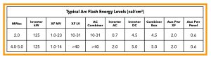
Many facilities, recognizing the complexity of arc flash labels, have implemented a two-level PPE system. The first level is a Category 2 (8 cal/cm2) standard work uniform that also requires gloves, a face shield and other PPE as needed. The second is full Category 4 PPE for the rare occasions when Class 3 or 4 work is necessary. Without retraining, most employees can remember their regular uniform plus gloves and a face shield without issue.
Since there is little variation in arc flash energy levels among similar PV projects – and they are all quite similar – it may be relatively easy to establish a common set of practical arc flash labels for a given fleet of solar projects. Looking at the table above, they should prohibit hot work on any AC equipment upstream of the string inverters. All DC equipment is in the realm of typical Category 2 work clothes. That lower energy risk can be further reduced by work practices and their timing.
Conclusion
Engineers can calculate short-circuit currents and produce arc flash labels at any time, but they aren’t frequently consulted to assist in converting their dedicated efforts into safe, effective work practices. Arc flash labels don’t provide any guarantees, and human performance is far more critical to safety than the presence of a few labels. Ideally, PV owners will continue to use arc flash labels while also developing work methods and investing in equipment to ensure worker exposure to energized system components is a rare occurrence – one that requires a thorough preliminary review and a written hot-work permit.
About the Author: Joe Jancauskas, P.E., CUSP, PMP, has over 40 years of electrical power engineering experience, including 16 years in solar. He has been responsible for numerous arc flash studies as well as implementing an effective arc flash program for an electric utility.