
Detecting Shock Hazards at Transmission Line Work Sites
The line crew’s job for the day is to replace a 115-kV wooden H-frame transmission structure. No problem – this crew has done this type of work a number of times in the last few years. Upon arrival at the job site, the bucket truck and crane are arranged according to the job plan. A tailgate safety meeting is conducted, during which the clearance is reviewed and the points of isolation are identified. The work procedure is analyzed, including a discussion of the possible hazards and grounding plan for this work site. It is noted that, although not visible from this work site, this transmission line does share a right-of-way with two other high-voltage transmission lines about 15 miles from the work site. Induction could be an issue on this job. Maintaining a proper equipotential zone is emphasized.
At the conclusion of the tailgate safety meeting, the job proceeds according to plan. A work site ground is created by driving a temporary ground rod and bonding it to the pole grounds on the old structure. The ground rod is located directly under the center phase conductor, near the front bumper of the bucket truck. The bucket truck and crane are grounded to the temporary ground rod. The phase conductors are then grounded to the temporary ground rod.
The work proceeds without delay. Phase conductors and overhead ground wires are unclipped and lowered to the ground. Due to the spacing between structures and the structure height, the unclipped phase conductors remain about 2.5 feet off the ground. Everyone on the job site is reminded of the tripping hazard posed by this condition. The old structure is dismantled and removed.
A Severe Shock
After lunch, while setting up to drill the holes for the new structure, a lineman crosses behind the bucket truck to get to the other side of the work site. So as not to stumble over a phase conductor, he grabs it to steady himself as he steps over it. He suddenly receives a severe shock and is knocked to the ground.
What just happened? From the line crew’s perspective, they’ve replaced this type of structure before using the identical work site setup and work procedure. No one had ever received a shock. The equipotential work site grounding was set up correctly. So why did this shock accident happen today?
Ground Potential Rise
The root cause of this type of shock accident is GPR – not ground penetrating radar, but ground potential rise. GPR occurs when electric current is injected into the soil at the work site. The current flowing through the resistance of the soil causes the potential of the soil, relative to a remote earth, to rise, with the maximum potential located at the point of injection. GPR causes shock hazards at the work site that are more commonly referred to as step voltage, touch voltage and transfer touch voltage. Step voltage is the potential difference between two points on the earth’s surface separated by a distance of one pace, assumed to be 1 meter, in the direction of maximum potential gradient. Touch voltage is defined as the potential difference between a grounded metallic structure and a point on the earth’s surface separated by a distance equal to the normal maximum reach, approximately 1 meter. Transfer touch voltage is a special case of touch voltage where a conductive element – such as a vehicle – grounded to the structure brings the potential from the structure to a point spanning more earth than 1 meter. The transfer touch voltage increases as the distance from the grounded structure or equipment increases.
Figure 1 depicts the relationship between GPR, step voltage and touch voltage where the work site ground electrode is a single ground rod. Figure 2 depicts the relationship between GPR and transfer touch voltage.
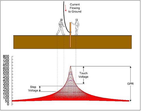
Figure 1
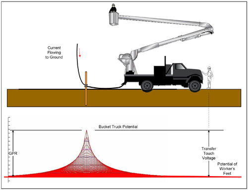
Figure 2
Determining GPR Severity
Two factors determine the severity of GPR:
1. The magnitude of the current injected into the work site ground.
2. The resistance between the work site ground and remote earth.
Let’s first consider the injected current. The largest injected current would occur should one or more of the phase conductors become energized. Full system fault current would flow to ground at the work site, usually thousands or even tens of thousands of amperes. Even for a moderate level of fault current, such as 3,000 amps, and a very low-resistance work site ground, such as 1 ohm, the GPR could rise to a lethal level approaching 3,000 volts. Although extremely rare, should this event happen, it would only last until the protective relays detected the fault and the circuit breakers isolated the line, approximately a half-second to one second. For a lineman to be exposed to this level of shock hazard, he would either have to be standing near the work site ground or be standing on the ground and touching something bonded to the work site ground when the conductors become energized.
A likelier source of current injected into the work site ground is current induced into the phase conductors from an energized parallel transmission line. The magnitude of the induced current can vary from as low as a half-amp to tens or even hundreds of amps. The factors that influence the magnitude of induced current include:
• The distance between the energized line and the de-energized line.
• The length of the corridor where the two lines are parallel – a few thousand feet or maybe 70-80 miles.
• The load current on the energized line.
• The number and location of ground connections on the de-energized line.
For the scenario above, a de-energized line paralleling two high-voltage transmission lines for 15 miles and a single connection to ground at the work site may have no more than 1 to 2 amps of injected current. So if the resistance of the work site is only 1 ohm, based on the previous example, the maximum GPR that could be developed is 1 to 2 volts. That’s not much of a shock hazard. However, unlike current from an energized conductor – which only lasts until the line is de-energized – if induced current exists, it will continuously flow to ground at the work site. Induced current is also not constant. The magnitude of the induced current will change as the current flowing on the energized parallel line changes.
Work Site Ground Resistance
The resistance of the work site ground can vary from low values around 10 ohms to extremely high values of 1000 ohms or more. The resistance of the work site ground is determined by the soil conditions at the work site and the configuration of the work site grounding system. Soil conditions will vary geographically as well as seasonally. Wet, loamy soil has very low resistance, whereas dry, sandy, rocky soil has very high resistance. Soil conditions can change drastically from one work site to another on the same transmission line right-of-way. On any given day at any given location, there is little that can be done to significantly change soil conditions. However, it may be possible to lower the resistance between the work site ground and remote earth by changing the configuration of the work site ground. The resistance of a single ground rod in dry soil can easily be 500 ohms or greater. However, by driving additional ground rods, separating them by the length of the ground rod and bonding them all together, the resistance of the work site ground might be reduced. Figure 3 shows a comparison of the GPR produced between a single ground rod and four ground rods.
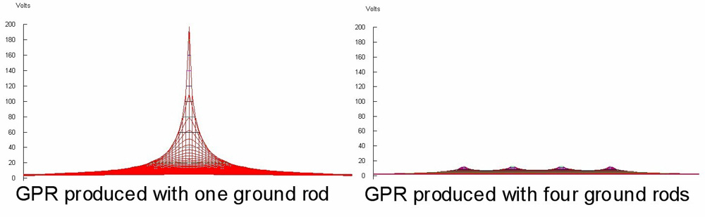
Figure 3
Unfortunately, soil conditions at some work sites are such that even with a work site ground consisting of four or even five ground rods, the ground’s resistance is still several hundred ohms.
An Examination of Resistance
In the scenario described at the beginning of the article, it states that the line crew established a work site ground by driving a temporary ground rod and bonding it to the pole grounds on the old structure. Let’s examine the resistance of this work site ground, beginning with the temporary ground rod. The soil at this work site is dry and consists of a mixture of clay, sand and small rocks. The resistance between this ground rod alone and remote earth is about 500 ohms. Connecting the pole ground on the two poles of the H-frame structure to the ground rod incorporates them into the work site ground and results in a total resistance of about 30 ohms. So if the resistance of the work site ground is only 30 ohms, what caused the shock accident described in the scenario mentioned earlier?
Before the old structure was removed, the induced current of 1 to 2 amps flowing through a work site ground with a resistance of about 30 ohms resulted in a maximum GPR of just under 60 volts. Given the standard gloves and footwear, a worker walking around the work site making contact with objects connected to the work site ground – such as conductors or equipment – would not feel any electric shock. Now the old structure is removed from the work site, and the connections are removed between pole grounds on the old poles and the temporary ground rod. This changes the configuration of the work site ground to a single temporary ground rod, which has a resistance of 500 ohms. However, the induced current flowing into the ground at the work site has the effect of drying out the soil, causing the resistance of the soil surrounding the temporary ground rod to gradually increase as the day progresses. The resistance at the time of the shock incident is probably greater than 500 ohms. Also, it is quite possible that loading on the energized lines, which parallel the line being worked on, also increased as the day progressed. Higher induced currents flowing through a high-resistance work site ground resulted in a GPR at the work site that was high enough to represent a serious shock hazard to the workers. When the lineman grabbed the conductor to step over it, he placed his body between two objects at different potential. The conductor was at the potential of the work site ground, which was being influenced by the GPR, but the soil he was standing on was at a much lower potential.
Protection Against GPR
How can lineworkers working in this type of environment be protected from the hazards created by GPR? This is a question my employer, Western Area Power Administration, has wrestled with for several years. One option for lineworkers standing on the ground is to avoid contact with the work site ground or anything connected to it. It’s an idea that is good in theory, but it’s not very practical. Since it’s very difficult to include the soil at the work site in the equipotential zone, insulating a lineman from the soil would protect him should he make contact with anything connected to the work site ground. However, experience has shown that this extra level of protection is not required all the time. The ideal situation would be to know when extra protection is required. This is a challenge that Western undertook. The GPR monitor was developed to provide real-time monitoring of work site GPR. The instrument provides a warning to lineworkers when work site GPR rises to a level that requires additional protection.
The GroundHound
After field testing the proof-of-concept prototype, the GPR monitor technology was licensed to Advantage Electronic Product Development (www.advantage-dev.com) for commercial development. The GPR monitor – marketed by Advantage as the GroundHound – consists of a sensor unit and a handheld remote. The sensor unit is placed on the work site and connected between the work site ground and a reference probe installed at least 20 feet from any ground electrode. The sensor unit provides real-time monitoring of the work site GPR. The sensor unit is designed to alarm both visually and audibly when the GPR has reached a level that requires additional protection and the GPR level is too high to continue working using de-energized work practices. A depiction of the GPR monitor installed on a transmission line work site is provided in Figure 4. The sensor unit monitors ground potential as depicted in Figure 5. If the GPR at the work site exceeds 75 volts, caution lights on the sensor unit begin to strobe to alert the line crew that significant GPR is present. If the work site GPR exceeds 100 volts, an audible alarm is sounded. This indicates that the work site GPR has reached a level that requires additional protection. If the work site GPR exceeds 500 volts, an alarm is sounded, indicating that the work site GPR has reached such a level that de-energized work practices cannot continue.
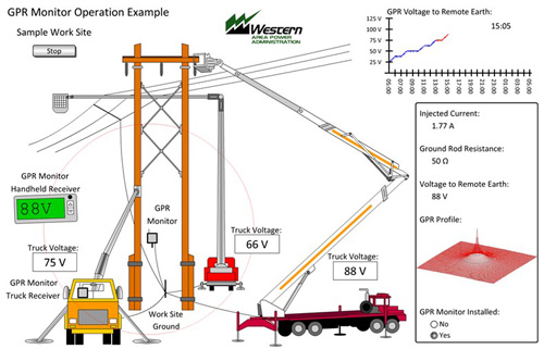
Figure 4
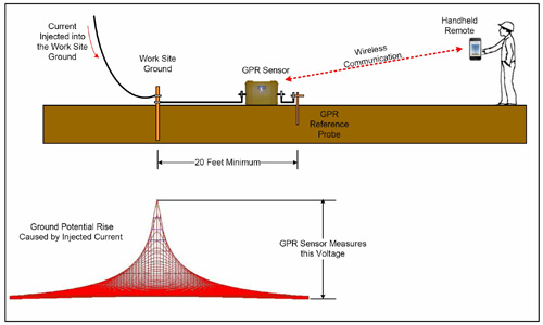
Figure 5
In addition to work site GPR, the sensor unit also monitors for high-energy transients. While field testing the proof-of-concept prototype, it came to Western’s attention that certain work sites were susceptible to large spikes in GPR caused by switching transients coupled into the grounded phase conductors. Small transients with correspondingly small energy content pose no hazard; however, some transients exceeded several thousand volts with an energy content of 80 joules or more. Based on a review of papers addressing transient shock hazards, it was determined that a transient containing more than 13 joules of energy poses a serious hazard. An example of a hazardous transient is provided in Figure 6.
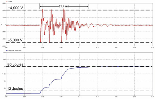
Figure 6
The sensor unit also contains an onboard data logger that provides for continuous logging of the work site GPR levels, complete with date and time stamps. In the event of a shock incident, the data log will provide the information necessary to determine if work site GPR played a role in the shock incident.
Leveraging Technology
Advantage leveraged existing technology in the development of the handheld remote. Instead of developing a dedicated handheld receiver, the company utilized iPhone hardware. A special holster was developed for the iPhone that allows the custom GPR monitor application to communicate with the sensor unit using the IEEE 802.15.4 ZigBee protocol. The iPhone app displays a numerical readout of the real-time work site GPR and a graphical indicator of the sensor’s battery level, and has the ability to acknowledge and clear the alarms. If a transient event is detected, the peak transient voltage and energy content are displayed with the iPhone app. In the future, an app and interface will be developed for Android technology as well.
If a GroundHound GPR monitor had been installed at the work site mentioned in the beginning of this article, the outcome would probably have been different. As soon as the old H-frame structure was disconnected from the temporary ground rod, the work site ground configuration was changed, resulting in a high-resistance work site ground. Even without changing the injected current levels, the work site GPR would have risen significantly. The GroundHound alarm would have alerted the line crew to the high GPR hazard. Instantly, the line crew would have had a more complete picture of the real-time shock hazards at the work site. This would have allowed them to suspend their work, reassess their work procedures and incorporate any additional safety precautions to ensure that the work could be safely completed.
About the Author: Gary Zevenbergen has worked for Western Area Power Administration for 24 years. He currently oversees Western’s grounding program and provides training on shock hazard recognition and personal protective grounding to the company’s line crews and electricians. Zevenbergen, a licensed professional engineer, is a member of IEEE and is active on the IEEE ESMO subcommittee.